Corning Varioptic Liquid Lens for Bar Code Reading Applications
A key element in automation processes that is used to track shipments is barcode. Barcodes have evolved over the years, from standard linear patterns to more complex QR codes that allow users to identify items and directly access associated data. Historical laser-based barcode readers cannot read 2D codes, which are becoming more prevalent. Laser scanners don’t decode well 1D barcodes that are either poorly printed, with low contrast, distorted, or damaged. These systems are gradually replaced by image-based barcode readers that guarantee a reliable reading whatever the conditions, the distance, and the format of the barcode. Incumbents of various industries and sectors, including manufacturing, retail, and industrial, are expected to aggressively deploy barcode technology for precise tracking of individual products and product batches as well as for auditing their inventories, thereby driving the growth of the market for the 2D barcode readers.
Technical Requirements of Barcode Readers
Two main types of system exist: fixed-mount and handheld barcode readers. In both cases the lens must not be sensitive to orientation. In the latter case, the lens should also endure the potential movements of the device during the scan. To achieve fast and reliable readings, barcode readers must be able to decode small patterns at different distances on moving items, such as packages on a conveyor belt. This operation needs to be done automatically, to prevent an operator from manually adjusting the lens in the field or on the production line. To be integrated into several types of environments with different working distances, the system needs to have a large optical power range of 10 or more diopters.
Barcode generalities
Barcodes quality is defined according to the following ISO standard:
• ISO14516 for 1D barcodes where a grade is determined after 10 scan lines taken along the length of the code, each scan line is graded, the average is taken for the overall grade.
.jpg)
ISO14516 grading method.
• ISO14515 for 2D barcodes, where the symbols are graded against 8 different parameters among contrast, modulation and uniformity.
.jpg)
The system needs then to acquire a good image of the code to analyze it quickly even with low-rated symbols. Resolution and quality of focus are key elements to ease the decoding of the code and to reach high reading rates.
.jpg)
Hence, the first item to check would be the required resolution of the sensor. It can be computed based on the smallest pattern to be decoded.
Technical definitions
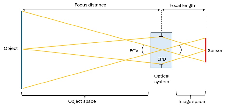
A conventional barcode reader is an optical system that converters a 2D object into an image. Rays emitted from the scene in the object space are captured by the lens and form a plane at the sensor location in the image space. The focal length of the optics, together with the sensor size, define the Field Of View (FOV) of the system. The F#, or f-number, is a dimensionless number that measures the light-gathering ability of the system. It is the ratio of the focal length divided by the entrance pupil diameter (EPD). It directly impacts the depth at which objects appear in focus (depth of field) as we’ll see later.
Required Resolution and Field of View
Barcodes are usually named X-mil. The X dimension is the width, in thousandths of an inch, of the narrowest element (bar or space) in a barcode. For instance, a .006" bar width would be referred to as a 6-mil label (0.152mm).
Due to the Nyquist-Shannon sampling theorem, the sampling frequency should be at least two times the maximum frequency of the object to be sampled. For a 6-mil barcode, the grid would have a succession of 0.152mm wide black lines and 0.152mm wide white lines. This corresponds to a frequency of 1/0.304 ~ 3.3 lp/mm in the object space. Therefore, the minimum target sampling should be 13.2 pixels/mm which represents 4pixels for 1line pair.
First example: A typical 6-mil barcode has a 19.5mm width and 14.5mm height. Let’s imagine we want to image this barcode located at 80mm. The horizontal field of view can be obtained using the following formula:
1280 x 960 pixels sensors are typical for this type of application. Let’s imagine we use such sensors for this case. The horizontal resolution can be computed using the equation:
The resolving power of the sensor at 80mm corresponds to 65.6 px/mm in the object space. Since the 6-mil barcode can be decoded if the sensor resolution is at least 13.2 px/mm. This sensor is suitable for this use-case and the HFOV could be up to five times larger and still allow the correct reading of the barcode.
Second example: With 14° field of view, we can compute the maximum distance at which a 30-mil barcode can be decoded. For this barcode, the minimum target sampling is 0.66 lp/mm, which leads a target sampling (or resolution) of 2.6 px/mm.
Hence a 30-mil barcode can be decoded up to 2015 mm. The following diagram shows the FOV and associated working distance:
Number of megapixels required can be found by multiplying the smallest object size with the resolution, hence for this application a required 0.76 x 2.6 = 1.98Mpx sensor would be required.
Effective Focal Length Calculation
With 14° field of view an associated EFL can be computed using the formula below:
.jpg)
The required lens effective focal length is then 19.2 mm at least.
Depth Of Field Determination
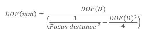
With these parameters, it is possible to determine the depth of field (DOF) in diopters of the optical system using the formula:
.jpg)
Note that the formula would be different for a color sensor since it has a Bayer matrix:
.jpg)
For our specific use-case with monochrome sensor, we would have a depth of field of 0.1 diopter. For an object at 1m, it represents a depth of field of 10cm. This result is obtained using the formula:
Certified System Integrator Program
Set Yourself at the Forefront of the Global Vision Market
.jpg) Vision system integrators certified by A3 are acknowledged globally throughout the industry as an elite group of accomplished, highly skilled and trusted professionals. You’ll be able to leverage your certification to enhance your competitiveness and expand your opportunities.
Vision system integrators certified by A3 are acknowledged globally throughout the industry as an elite group of accomplished, highly skilled and trusted professionals. You’ll be able to leverage your certification to enhance your competitiveness and expand your opportunities.
For an object at 100mm, it would represent a depth of field of 1mm, which is quite narrow:
Typical Solution and Associated Issues
Let’s assume we want to read a 6-mil barcode at 500mm distance with a high-speed camera in a warehouse. The optical system will be designed with an F# as low as possible to have optimized focus at the right distance and the capacity to acquire images rapidly. The problem with such a solution is that the MTF drops quickly when getting away from the optimized focus distance.
To read a barcode, the minimum contrast required by a machine vision algorithm is typically 20%. A 6-mil barcode for instance could easily be read at 500mm with 16mm lens with F/4. The MTF level is above the minimum contrast requirement as seen on the chart below (the green envelope corresponds to all the MTF curves from center of the field to maximum image height).
If this barcode now moves closer, for instance at 300mm, the object steps out of the depth of field and the MTF or contrast drops drastically (red envelope). The image appears blurry, and the barcode cannot be deciphered anymore.
A quick fix to increase the depth of field is to increase the F#. Moving to F/10, the MTF increases for the 300mm focus position (yellow envelope) but the improvement is not sufficient to effectively decode the object.
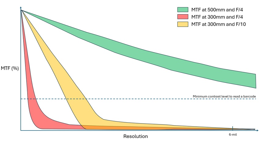
In this scenario, increasing the F# is not sufficient to get back to the nominal MTF performance obtained at the best focus. Additionally, the loss of light associated with the F# increase could negatively impact the initial goal to read the barcode with a high-speed camera since the exposure time would need to be increased as well. This solution is not suitable.
Liquid Lens Solution
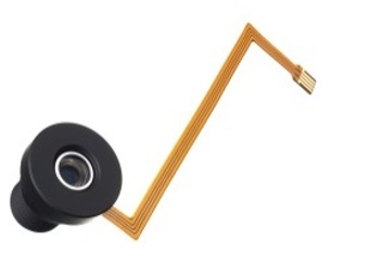
Corning Varioptic has developed an optical device called liquid lens that adjusts voltage to change the shape of a liquid interface. This technology based on the physical principle of electrowetting allows to perform autofocus with a single add-in or add-on element. By using two liquids of equal density, the lens is not sensitive to orientation. As there are no mechanical moving parts, this liquid lens can endure millions of cycles with a low power consumption and at a speed unmatched by conventional actuators. Its robustness and accuracy in performing autofocus makes it a perfect candidate for any application requiring large scale autofocus such as bar code readers.
Case Study
Let us take the example of a mounted barcode reader that need to decode 2D codes. Each code may have different format from 6 to 30 mils. The codes are located on packages which may have different size, hence can be located at different distance from the scanner from 80mm to 1000mm.
Example with a Corning Varioptic C-S-39N0-158 lens
Corning can offer a variety of liquid lenses-based module with different focal lengths and format. With its 15,8mm focal length F/4 and 22° angle field of view for 1/3” sensor, C-S-39N0-158 liquid lens module could perfectly match this case. The module offers a wide optical range which makes it perfectly suitable for such application
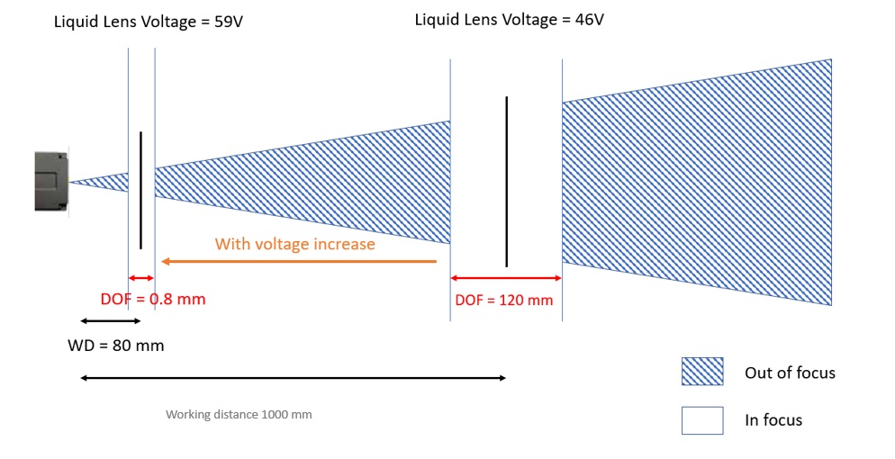
Using such liquid lens module would enable the barcode to support a working distance range from 7 cm to infinity with DOF of 0.8mm @80mm and 120mm @1000mm working distance.
With this liquid lens optical module, focus can be optimized at 500mm first. Then, once the object has moved to 300mm, the lens’ optical power can be tuned to obtain the MTF chart below. The green curve corresponds to the initial contrast at 500mm. The red curve shows the MTF drop due to the defocus when the object is at 300mm and the blue curves show how the system can adapt to the new focus distance and recover a high contrast value, sufficient to read a 6-mil barcode.
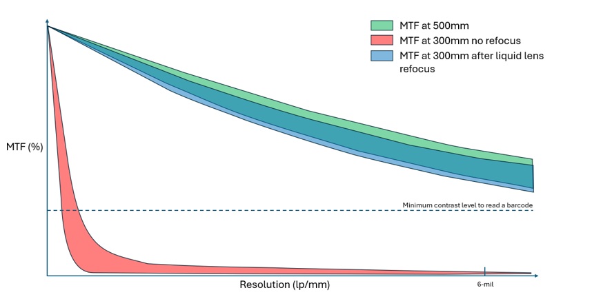
Thanks to the variable focus provided by the liquid lens, the 6-mil barcode can be read both at 500mm and 300mm.
Control Strategy
Different strategies can be implemented for such applications:
• Close loop approach where a processor runs a contrast optimization loop to maximize the sharpness of the image. This is the best approach to get the optimal image quality. The overall performance depends on many system parameters such as sensor frame rate and processing speed; typically, the complete auto focus loop can be completed in 8 to 12 iterations.
• Open-loop strategy for fixed-mount readers with predetermined working distances. A look-up table is filled with calibrated voltage value for specific working distance. Open loop driving enables ultra-fast focusing where focus can be achieved with one frame only. It however requires external hardware such as a ToF (Time Of Flight) sensor.
• Mixed mode: a combination of open loop for coarse search, and closed loop for fine tuning of the focus.
• Ramp algorithm for handheld bar code readers: The focus ramp is a linear change of the optical power of the liquid lens with time. Picture are taken while the liquid lens is still moving with virtually no settling time. Below you can see an example of a 20D ramp in a few hundreds of milliseconds with very low associated wavefront error (with liquid lens A-25H0).
The principle is to cover the full optical power range of the liquid lens and to decode and analyze the associated image on the fly. Actual ramp parameters depend on the envisaged system design, mainly DOF and integration time of the sensor.
Conclusion
The expansion of barcode technology and the diversity of pattern formats would lead scanners to increase their read rate performance and to adapt to different supply chain setups. Acquiring a good quality of image in a short time frames is then becoming a must-have to take up these challenges. Efficient autofocus is becoming a key element to achieve such performance.
Liquid lens-based devices allow the barcode reader to optimize its focus and hence maximize the sharpness of an image without any manual operation. This compact, low cost and low power solution can easily be integrated into optical stacks and extend the reading distance from a few centimeters to several meters. Additionally, liquid lenses benefit from a fast response time (few tens of ms), which make them perfectly suitable for such application.
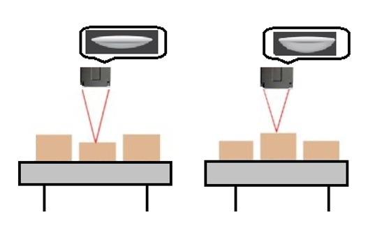
Without liquid lens in the optical system only a limited set of barcodes can be decoded at different distances
With liquid lens in the bar code reader described previously most barcodes can be successfully read at different distances
Corning Incorporated
Discover how Corning Incorporated can support your automation journey with their complete range of solutions and expertise.
Related Posts
esmo Achieves Precise Microchip Feeding with senswork Vision Technology
esmo relies on vision technology from senswork Ensuring precise feeding of microchips 26. March 2026…
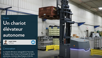
Noovelia Featured in La Presse: An Autonomous Forklift
La Presse: an Autonomous Forklift An autonomous forklift: NOOVELIA pushes the boundaries of the industry.…
Pleora Launches eBUS SDK 7.0, Delivering a Unified, High Performance Platform for Next Generation Imaging Systems
Pleora Technologies today launched eBUS SDK 7.0, expanding its industry-leading platform with enhanced tools for…
Leave a Reply